Data Flow Diagram in Software Engineering
Data Flow Diagram
The DFD is a simple graphical formalism that can be used to represent a system in terms of the input data to the system, various processing carried out on those data and the output data generated by the system.
The main reason why the DFD technique is so popular is probably that DFD is a very simple formalism, it is simple to understand and use. A DFD model uses a very limited number of primitive symbols to represent the functions performed by a system and the data flow among these functions.
Primitive Symbols used in DFD:
There are essentially five different types of symbols used for constructing DFDs.
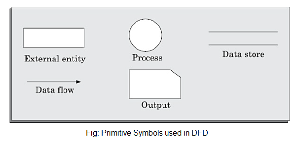
Function symbol: A function is represented using a circle. This symbol is called a process or a bubble. Bubbles are annotated with the names of the corresponding functions.
External entity symbol: An external entity such as a librarian, a library member, etc. It is represented by a rectangle. The external entities are essentially those physical entities external to the software system which interact with the system by inputting data into the system or by consuming the data produced by the system.
Data flow symbol: A directed arc is used as a data flow symbol. A data flow symbol represents the data flow occurring between two processes or between an external entity and a process in the direction of the data flow arrow. Data flow symbols are usually annotated with the corresponding data names.
Datastore symbol: A datastore is represented using two parallel lines. It represents a logical file. That is, a data store symbol can represent either a data structure or a physical file on a disk. Each data store is connected to a process using a data flow symbol.
Output symbol: The output symbol is used when a hard copy is produced.